TRACK CONSTRUCTION 2001

After school was out in early June, 2001, construction on the railroad right-of-way continued in the lower field.  Here the tower is installed and the cemetery has been completed.  Stephen has just finished installing rail from the crossing where he left off last year to the long turn by the cemetery at the west end of the property.

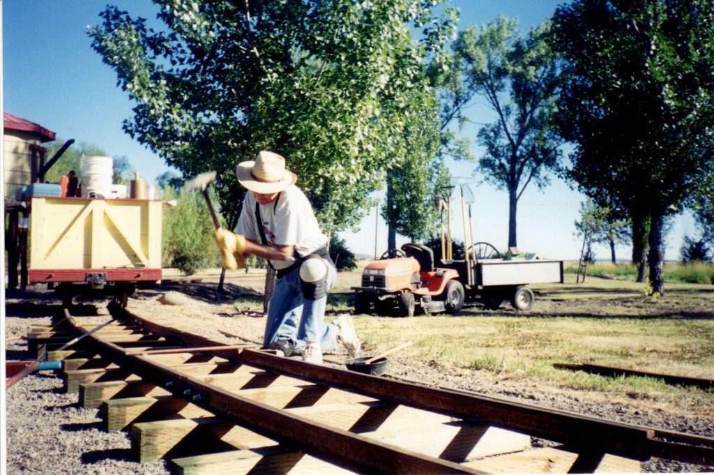
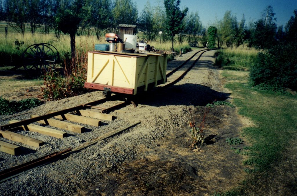
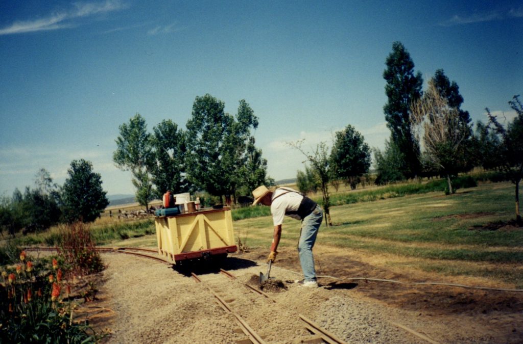
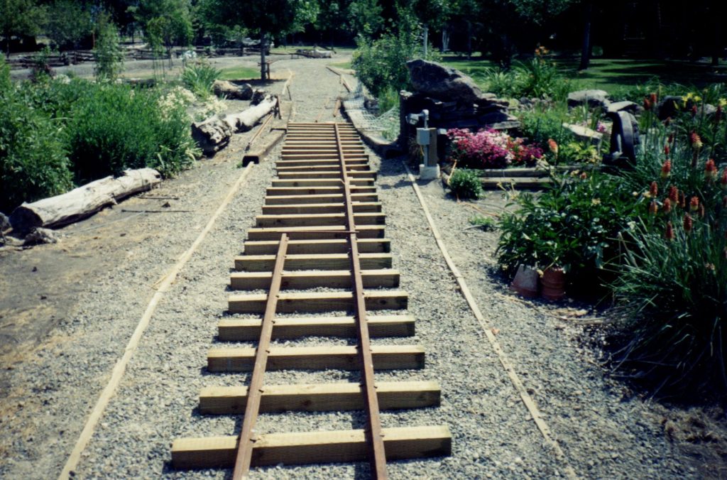
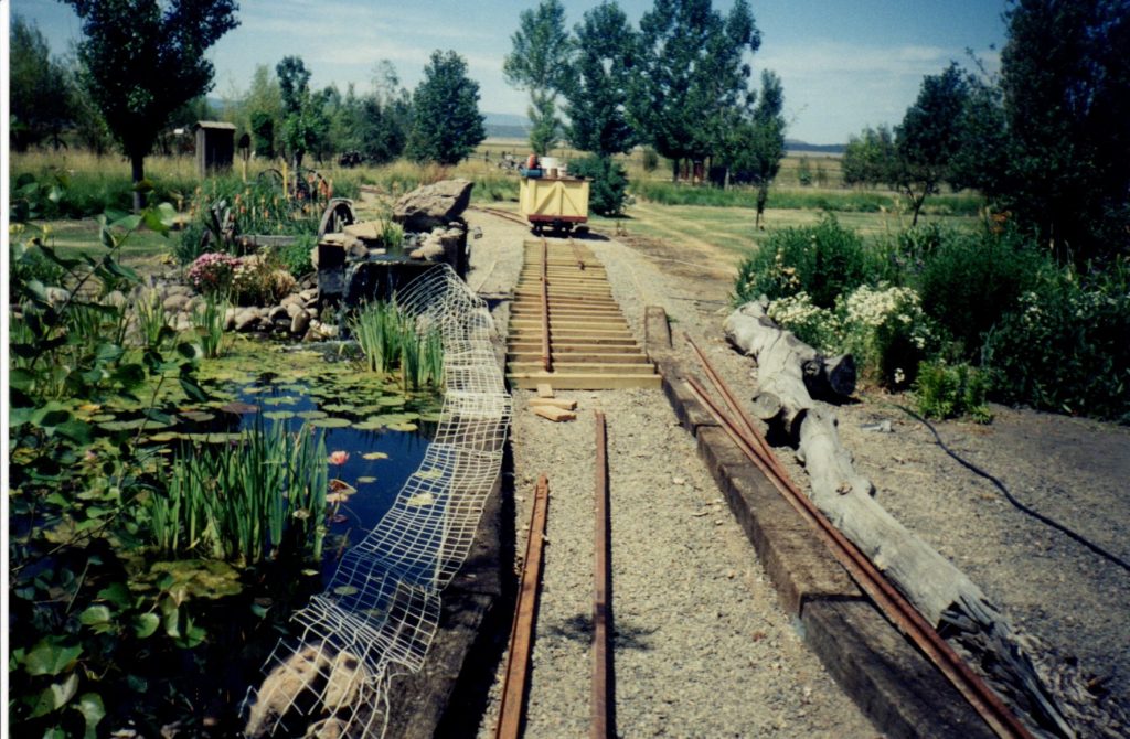
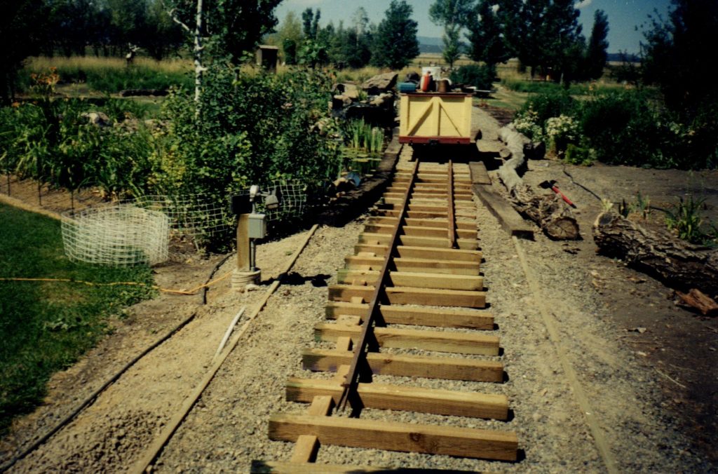
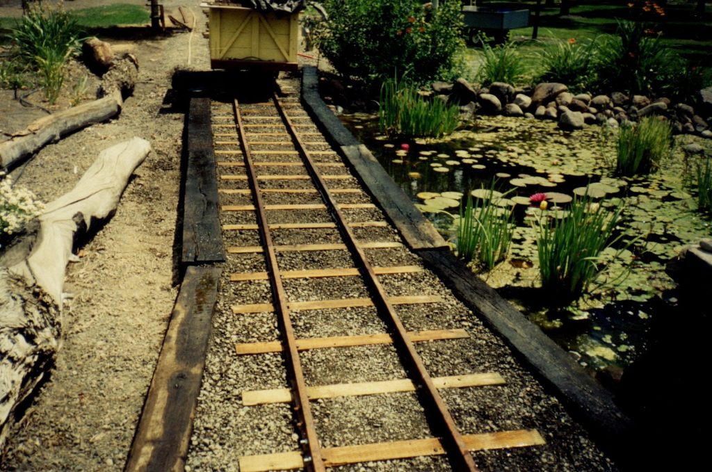
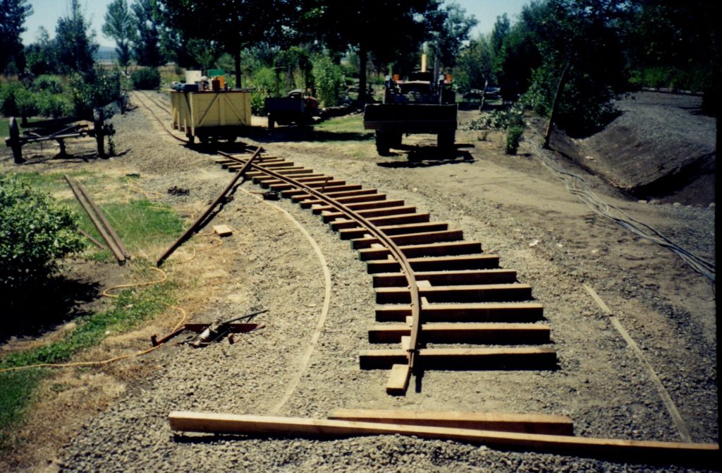
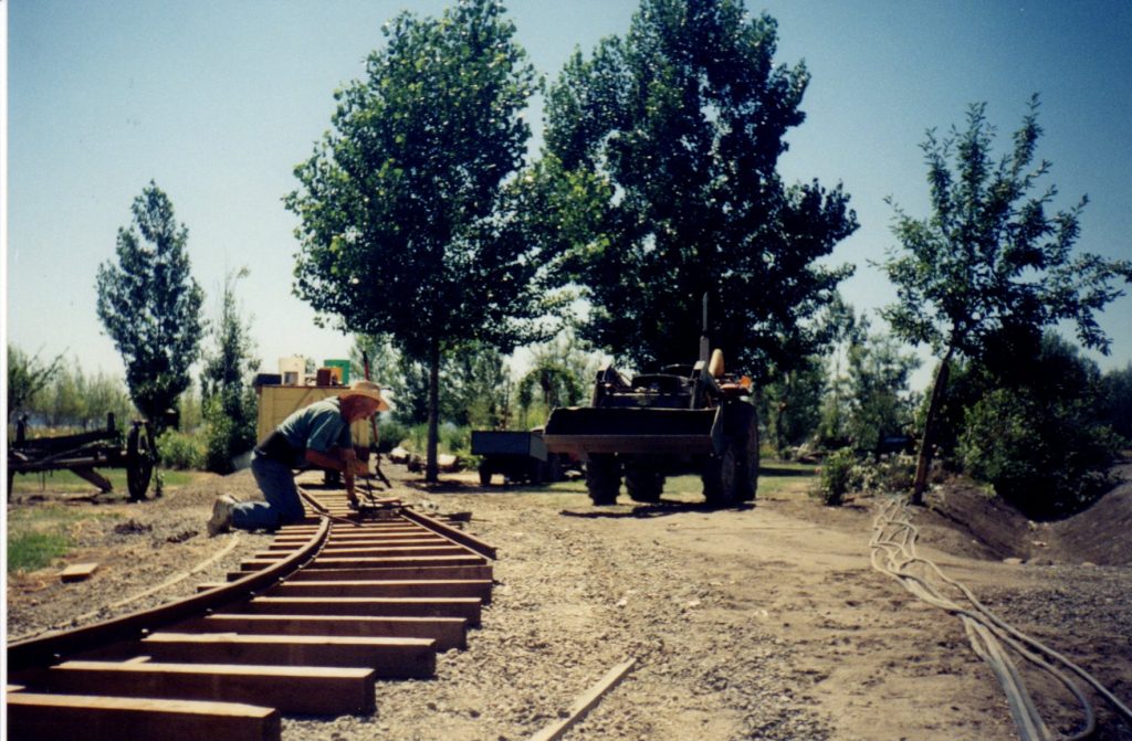
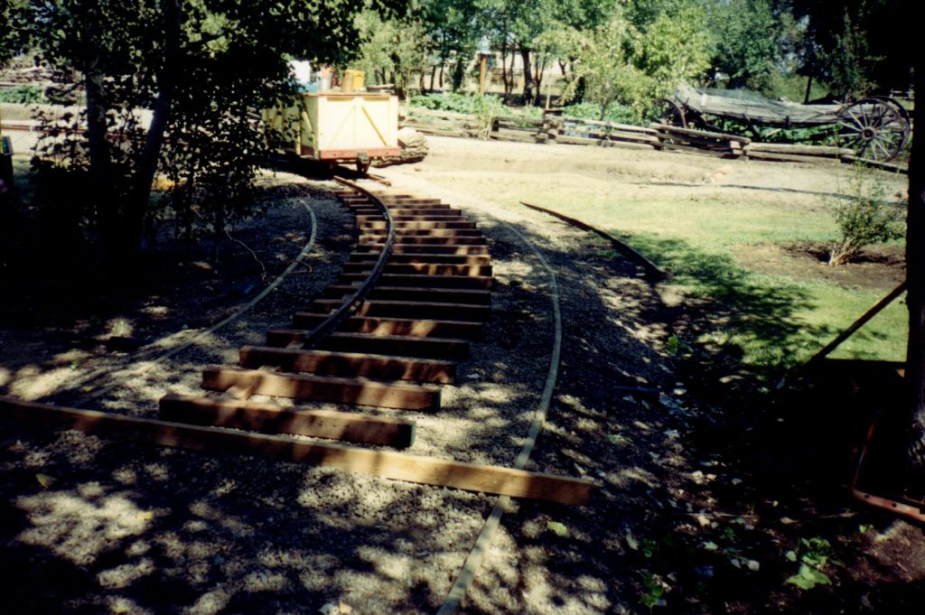
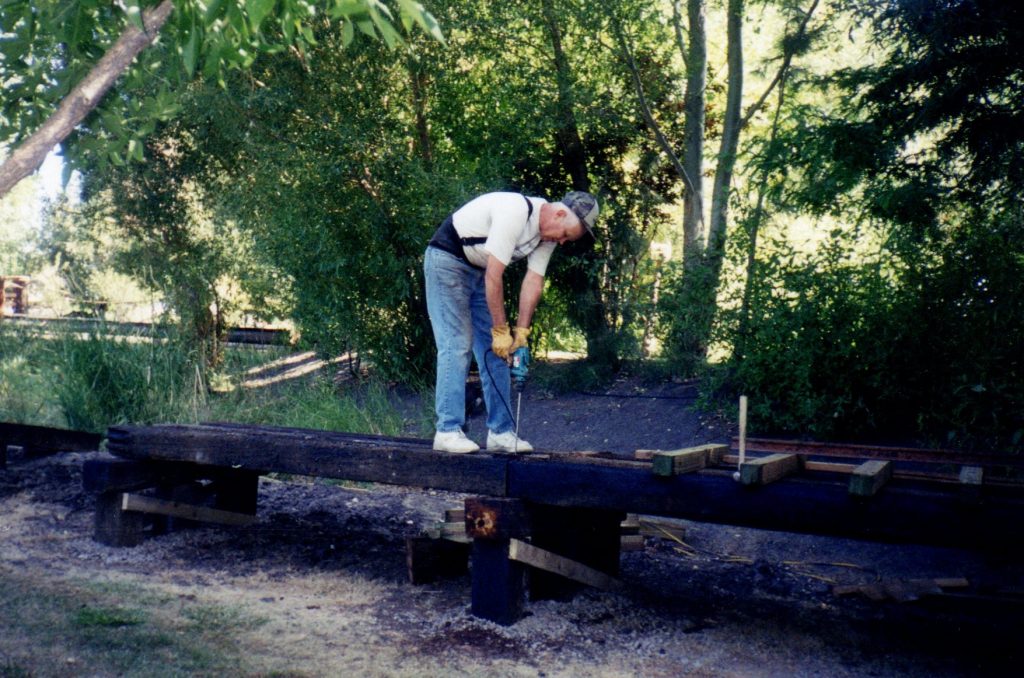
This photo shows Stephen driving railroad spikes across from the cemetery.  The yellow train car was used each summer as a “work car”.  It contained all the tools Stephen needed to install the track.  Tools included the rail bender, clamps, electric tools, spikes, and the ever present spike hammer.  Clamps were used to hold the rail in place while the spikes were being driven.

By mid summer of 2001, the roadbed finally completed the turn at the western end of the property and headed back toward the Observation Tower.

Here the track has crossed the second marsh at the western end of the property, and the rail is approaching the Wedding Pond.  

Once the rail was spiked down, Stephen would use the front end loader to dump road base on the track.  This last layer of road base had to be hand leveled.

Stephen later built the railroad arbor over this section of track, and the Hoist House and Assay Office were built where the track makes the long, slow turn.

The roadbed narrows as it approaches the crossing on the side of the Wedding Pond.

Crossing the Wedding Pond was hard, physical work, because the front end loader could not be used to haul materials due to the lack of access.

The completed track finally passes the wedding pond.  Stephen created the Wedding Pond for his son Joshua’s wedding in July of 2000.

In the above photo,  the railroad ties and rail are in place ready to be installed on the east side of the Wedding Pond.

When crossing the area near the wedding pond, a huge amount of road base fill had to be used in order to keep the railroad track level.

The photos above give you an idea of how much the rails had to be bent by Stephen with the rail bender to follow the curve of the roadbed.  Early on in the project, Stephen decided that he wanted the right-of-way to meander around the garden, not just make a long loop.  He estimated that the labor intensive curves added two years to the installation of the track.  This is the final curve before the Observation Tower.

Once the curve was completed, the fifth railroad crossing in the lower field was completed to allow vehicle access to the various areas of the garden.

In mid August the rails approach the Observation Tower.  Construction had to stop here until Stephen built the railroad trestle seen in the distance, which connected the Observation Tower in the lower field with the track that will eventually run along the south side of the pond.  

With only two weeks until Stephen had to return to the classroom, Stephen started building the trestle that would connect the rail in the lower field with the roadbed along the south side of the large pond.  This was an interesting project because the trestle had to be a long, curved structure rising six feet in elevation.  All the railroad ties used in the trestle are oak to provide extra strength.

After the first row of ties were installed, they were sawed off to match the rise in elevation.  The portion of the railroad tie that was cut off was then cut to size and used as the horizontal cross member on top of the three support posts.

To ensure that the trestle could carry the weight of the train and passengers, Stephen added an extra center support to the structure.  Then cross braces were added to the three supports to prevent horizontal movement.

In the above photo, railroad ties are sitting on the roadbed by the pond where it meets the upper end of the trestle. The ties still have to be leveled to match up with the trestle.  You can see the temporary 16″ spacer blocks that keep the ties from shifting.

Stephen could not have built the railroad without the trusty help of his small tractor which is fitted with a front end loader and small backhoe.  In the photo above, Stephen is using it to lift the heavy solid oak railroad ties into place on top of the support posts.  The front end loader also carried the tons and tons of road base and hauled the iron rail to make this project possible.

After the railroad ties were in place, Stephen drilled them and fastened them down to the cross members with long galvanized spikes.

In the photo at the upper left you can see where the trestle meets the roadbed on the south side of the pond.  The picture on the right shows the trestle as it makes the long, slow, downward curve toward the lower field.  The railroad rail sitting on top of the ties was used to make sure the ties were level.  In the right hand photo Stephen is ready to drive the long galvanized spikes through the railroad ties to fasten them to the trestle supports.  Each tie has three spikes holding it in place.

This photo show a good cross section of how the trestle was built.  You can clearly see the three vertical supports which were buried three feet in the ground.  Then the cross support was attached on top of the ties.  Next, two angled cross supports were attached to prevent horizontal movement.  Then the 4″ x 4″ x 42″ railroad ties were attached on top in preparation for installing the rail.

The trestle was finally finished as it reached the elevation of the lower field.  Stephen put his tools away for the season, and the rails would have to wait until the spring of 2002 to be installed.