TRACK CONSTRUCTION 2000

Units of pressure treated 4 x 4 x 84″ posts arrived by the truckload over the next five years.  Stephen cut the posts into two 42″ pieces.  The exposed ends were soaked in preservative, and then the “railroad ties” were laid out on the leveled roadbed.  They were spaced 16″ apart with spacer blocks, and then the 20 lb. rail was laid out on top of the ties.

Before the project was completed, approximately 3,960 railroad ties had been installed. Since each railroad tie required four railroad spikes, Stephen pounded around 15,840 spikes over the five years of track installation.

                                                                                    ANCHOR CHAIN RAILING

There is an interesting story behind how Stephen and Cheryl ended up with piles of WW II anchor chain on their property in Alturas.  In the 1960s, a local purchasing agent for the United States Forest Service purchased some military surplus chain through a catalog.  He apparently thought he was buying tow chain.  He clearly didn’t read the information in the catalog correctly, because stacks of anchor chain arrived on a flatcar at the local Southern Pacific Railroad Depot that summer.  One piece of the anchor chain was eventually used on Devil’s Garden hooked between two Caterpillar tractors to knock down Juniper trees.  The rest of the chain was stored in the local USFS warehouse and forgotten.

Fast forward to 1999 when Cheryl was attending a USFS surplus auction in Alturas.  She saw the piles of anchor chain and called Stephen at work.  He asked her to buy it for their property.  Cheryl won the high bid, a forklift loaded it on a CSAA tow truck, and the driver brought the chain to our property where he dumped it in a big pile.

In June of 2000 Stephen had a large backhoe hook onto the anchor chain and slowly drag it to the location where he wanted to install it.  Anchor chain does not get tangled due to the cross piece welded in the center of each link.  So the chain easily unraveled from the large pile where it had been sitting for a year.  

In the photos above, the anchor chain snakes around the end of the barn and then arrives along the roadbed between the barn and the train tunnel.

Stephen then installed the anchor chain on posts along the railroad roadbed as a safety barrier between the railroad track and the walkway along the pond.

Before the rail could be installed, it had to be distributed along the railroad right-of-way along the completed roadbed.

Distributing the rail along the roadbed was a very difficult task since some areas could not be accessed with the tractor.  Since each rail weighed 120 pounds,  Cheryl (and their son Will when he was home) helped Stephen lift the rails onto the front end loader. The rails were then distributed along the roadbed around the property.  

Since the rails were 18′ – 20′ long, maneuvering around existing landscaping was a challenge.  Stephen worked on this part of the project until all of the 20 pound rail was moved out of the yard.  This was enough rail to go from the barn past the cemetery in the lower field.

Stephen was happy to finally starting to install the rail heading out the back end of the barn.  The first stage was to install a railroad switch so cars could be moved to a railroad siding to store cars when needed.

The railroad rail used in this project does not just “bend” on the curves.  Stephen had to use a rail bender which consisted of a hydraulic jack installed on an iron frame with two arms that reached over and hooked on the rail.  The jack was attached to a cross piece at the bottom of the contraption.  When Stephen jacked the handle on the jack, the rail would slowly (very slowly) start to bend.  He had to match the curve to the “exact” bend of the opposite rail.  This was a time consuming and difficult process.  Then a track gauge would be used to make sure the inside of the two rails were exactly 18″ apart.  If not, Stephen had to go back to bending the rail.  

When the two sides matched, the rail would be spiked to the railroad ties.  Over time Stephen learned to judge how much the rail was bending based on the amount of rust popping off the rail when it started to bend.

Stephen used smaller 10 pound mining rail on the sidings because the sidings would not need to be as sturdy as the main line.  This is the size of rail that ore cars operated on in mines.

In the two photos above the switch is completed, and Stephen can finally starting laying rail heading for the railroad tunnel.

 After several weeks of hard work, the railroad track extends from the switch at the back of the barn to the beginning of the 82′ railroad tunnel.   

In this photo you can see on the straight stretches Stephen used 4″ x 4″ x 20′ lengths of lumber to keep the railroad ties even while the spikes were being driven.  

The driving of the railroad spikes was all done while Stephen was on his knees with a short handled spike hammer.  He wore out several pairs of contractor’s knee pads during the five years of construction.

Early August was a very exciting time on our railroad.  Enough track was finally installed so Stephen and Cheryl could ride the train on a completed stretch of track from the barn to the railroad tunnel.

As soon as the track passed the railroad tunnel, Stephen started installing the sides and roof on the 82′ structure.  The rough 2″ x 12″ x 12′ pine boards were cut by a small local mill.  The roof was then covered with galvanized roofing.

Because of the bats, bugs, and other assorted creatures that hang out in the tunnel, it has become a tradition for young students on field trips to scream as the train passes through the long, dark tunnel.

The next section of roadbed that Stephen tackled was west of the railroad tunnel heading into the lower field. In the foreground you can see the 16″ spacer blocks were placed between the railroad ties to keep them spaced properly.

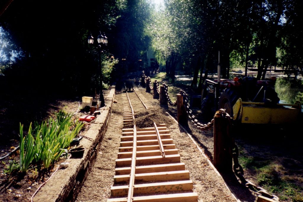
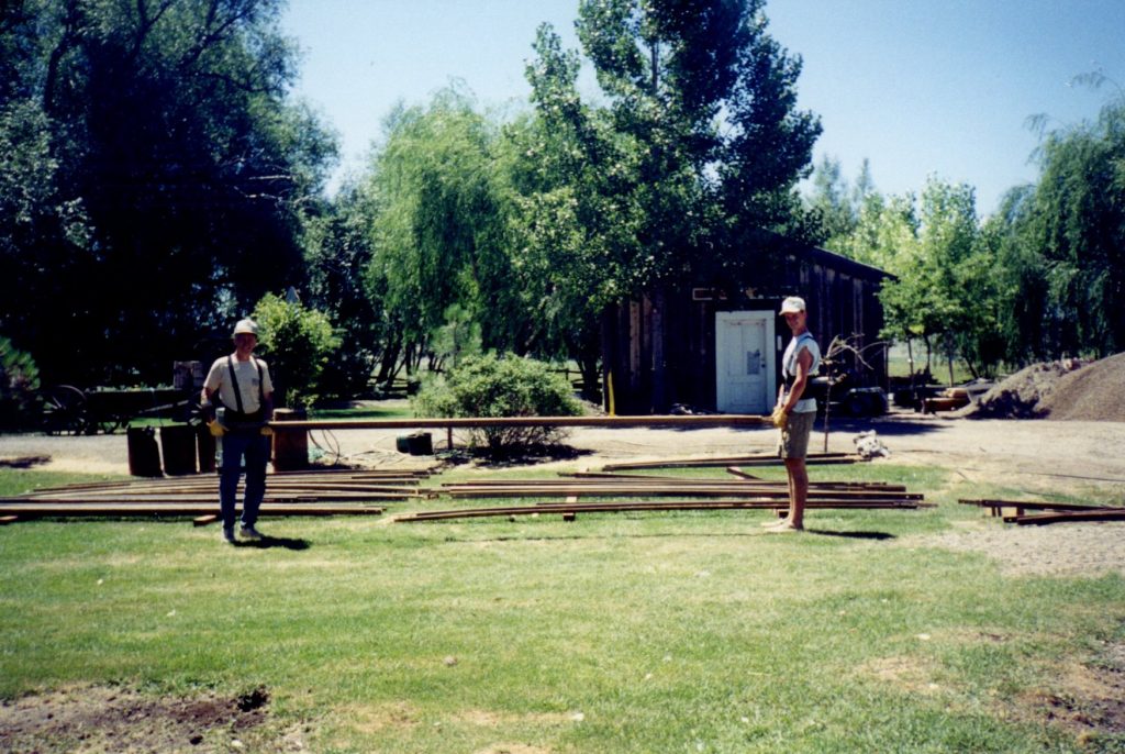
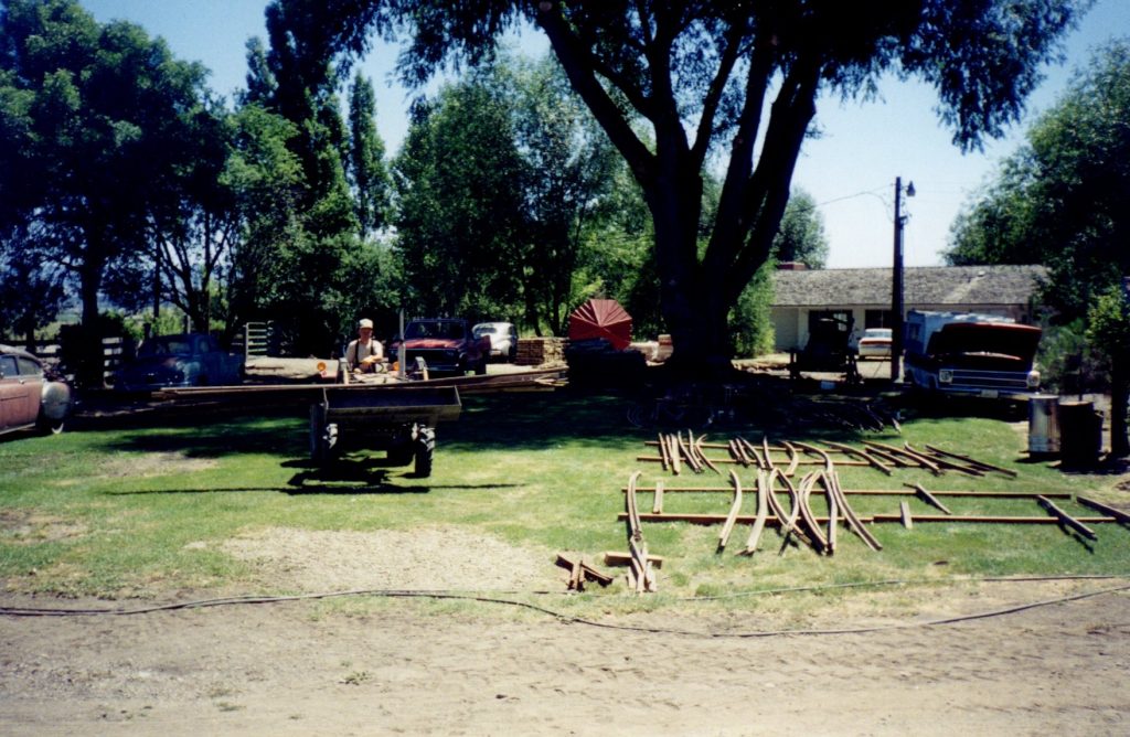
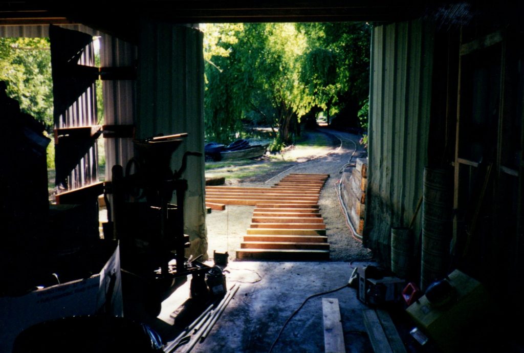
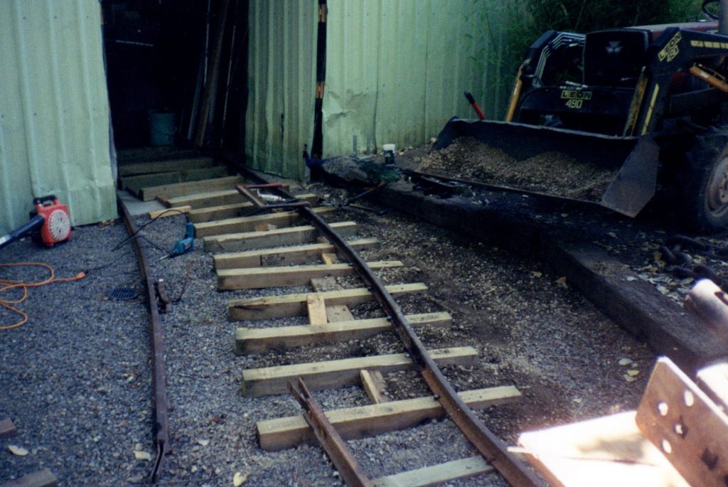
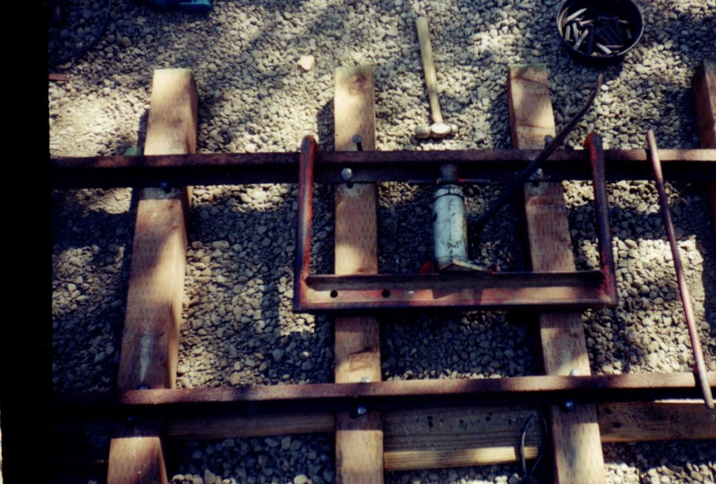
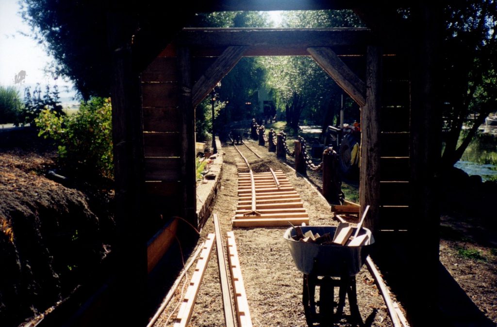
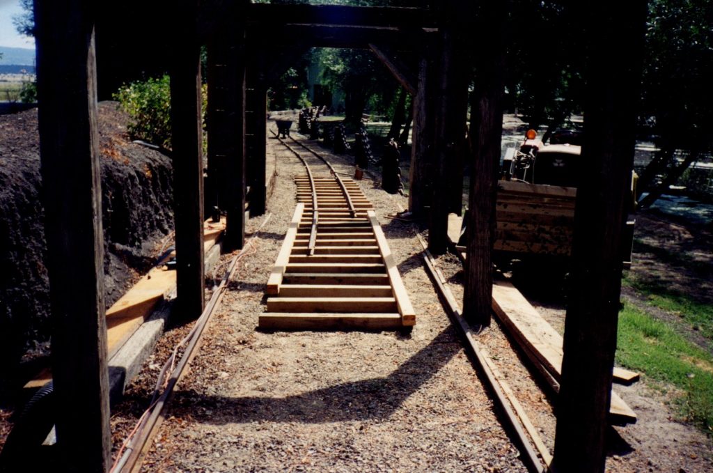
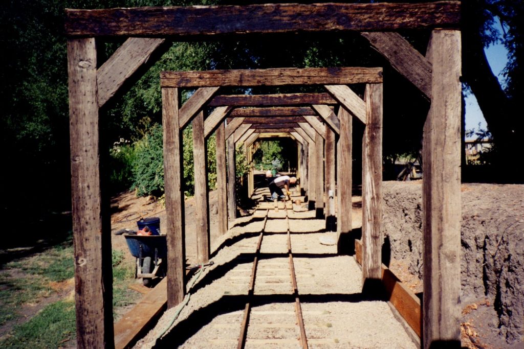
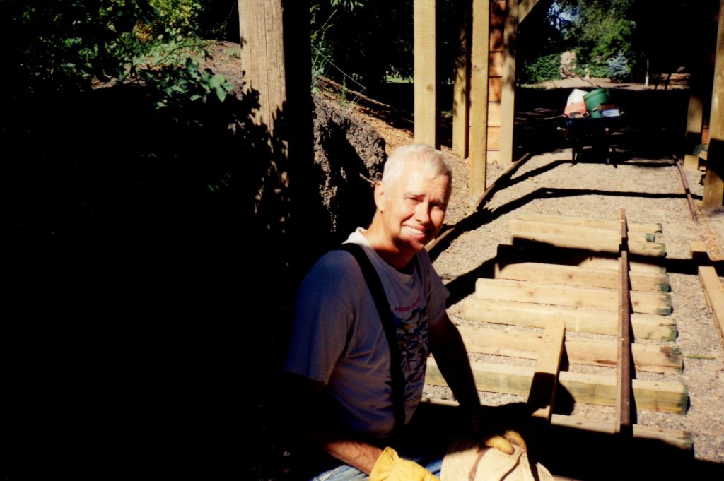
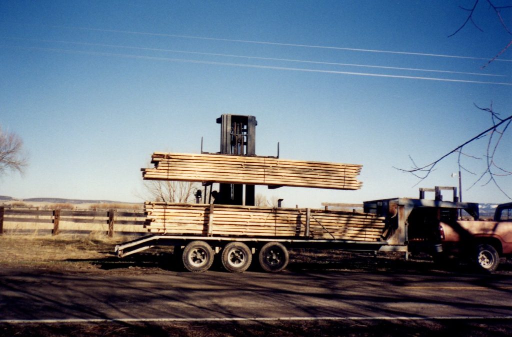
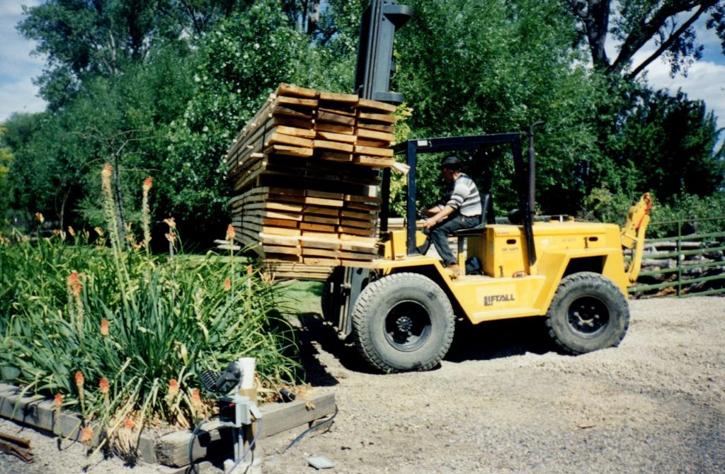
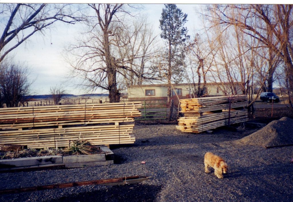
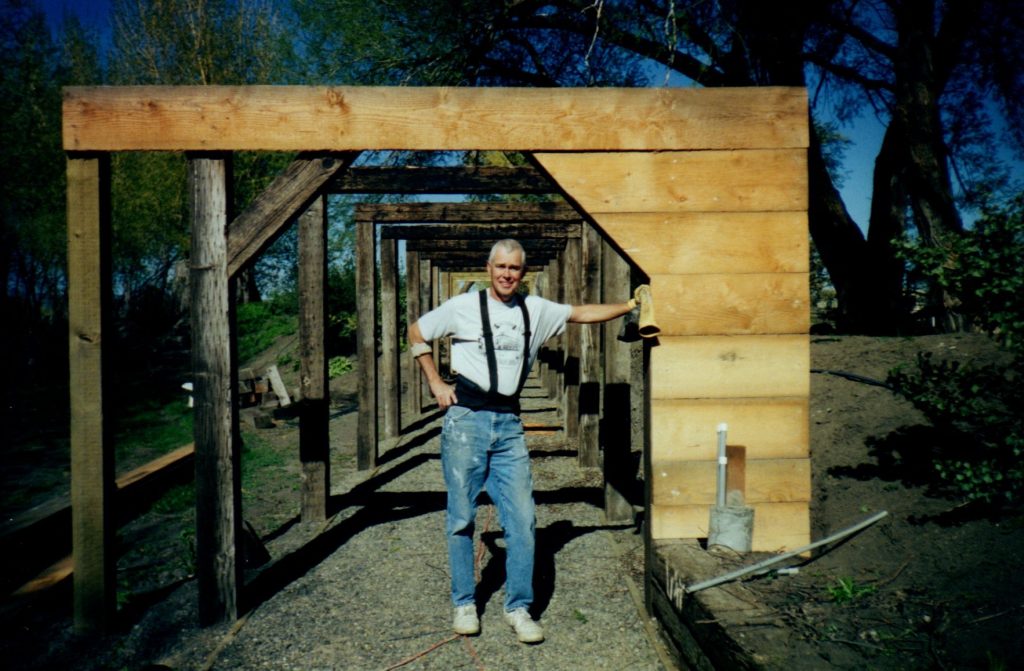
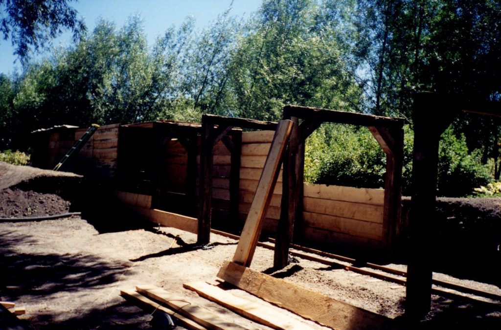
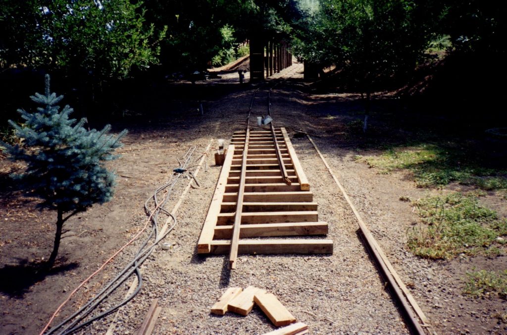
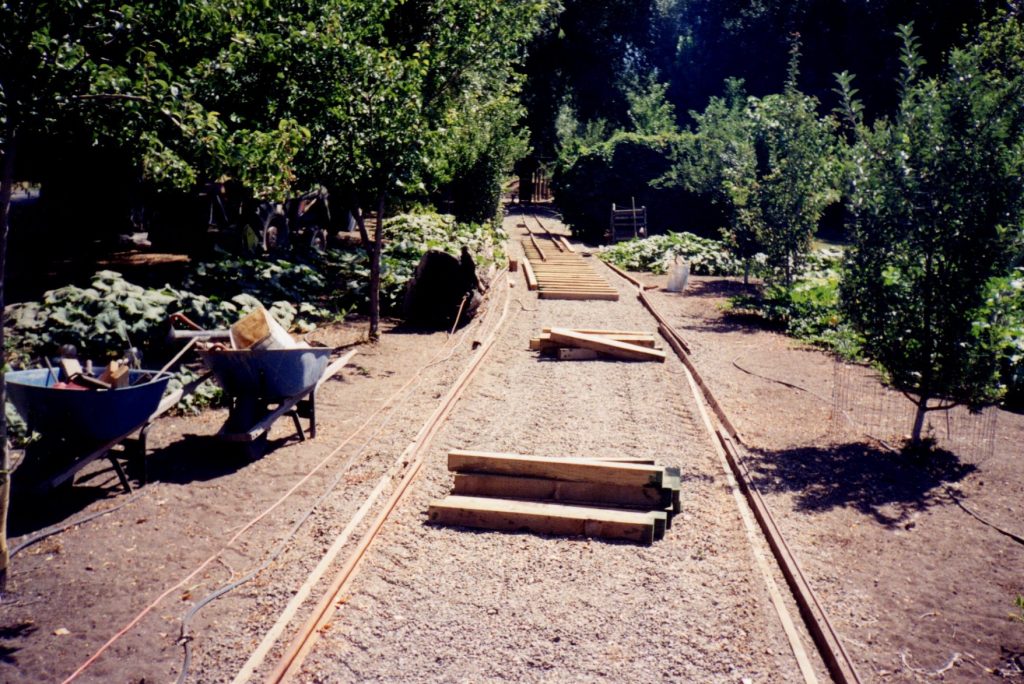
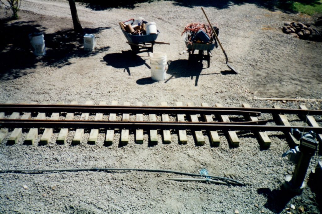
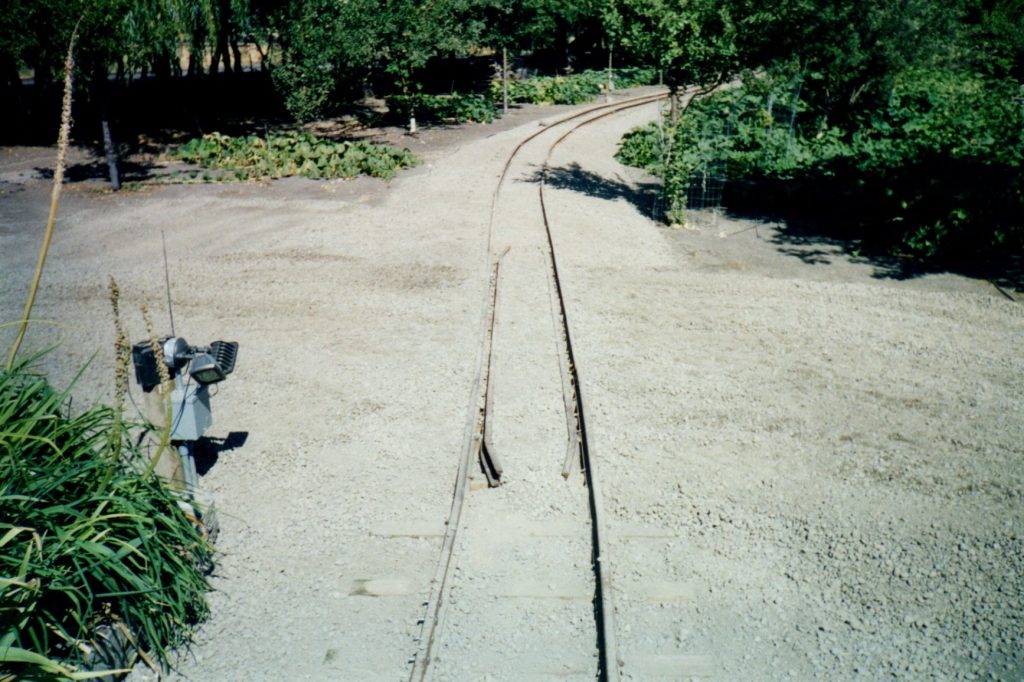
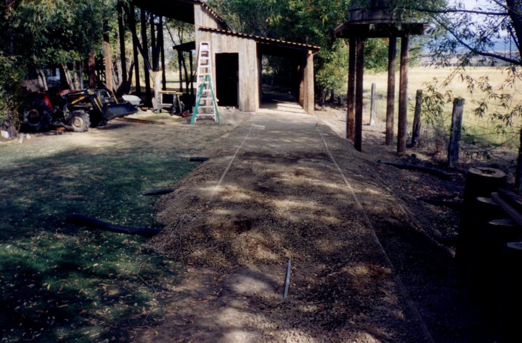
This photo provides a good example of how Stephen worked on the right-of-way in an assembly line fashion. The roadbed for this stretch had been completed, and the rail distributed along it, in 1999. Stacks of railroad ties were then placed along the middle of the roadbed. The railroad ties were then centered between the wood 2 x 4s that formed the sides of the roadbed. Rails were then lifted on top of the ties. The first rail was then bent as needed to conform to the curve of the roadbed. After it had been connected with a splice bar to the rail before it that was already spiked down, the new rail was spiked down. Splice bars are matching pieces of iron with pre-drilled holes which match the holes in the rail. They fit on either side of the two pieces of rail and were connected with four bolts. Next, the second rail was bent to conform with the first rail, it was connected with a splice bar to the previous rail, the rails were spaced 18″ apart, , and then then the second rail was spiked down.

At the end of each day, Stephen would celebrate by driving the train forward to the end of the track he had finished that day.  When Stephen started the railroad project, Cheryl gave him an engraved rock which had this inscription carved into it:  “Joy is found along the way… not at the end of the road.”  Stephen would move this rock every evening to the end of the track.  The engraved rock can be seen in the photo above on the ground near the light in front of the train engine.  The railroad spacer bar used to maintain the 18″ gauge of the rails can be seen between the rails in front of the train.

In this photo the roadbed has been leveled out in the lower for a driveway to cross the tracks once the rail passes this area.

In the middle of August, Stephen installed a railroad crossing when the track reached the roadway in the lower field. 

This closeup of the rail installed on the crossing illustrates how a crossing works.  By adding the second set of rails inside the outside rails, just enough space is left for the flanges on the railroad car wheels to roll through.  Then the center and outside is filled with road base allowing vehicles, lawnmowers, and people to easily cross the tracks smoothly.

ROADBED CONSTRUCTION SOUTH SIDE OF POND  AUGUST 2000

The final project of 2000 was to finish the roadbed between the Observation Tower, where work was stopped last August, and the Aviary.  

As the completed roadbed passes along the south side of the pond, you can see one of the light posts that was installed every 100′ along the roadbed.  A second post can be seen in the distance.

As the roadbed reached the area where the Aviary would be built, a retaining wall of telephone poles was installed along a slope on the property so a level roadbed could be built.  In the background you can see some of the stacked railroad rail that was located and purchased in Eureka the year before.

Stephen decided to build a third water tower along the railroad right-of-way for another redwood water tank he had purchased at an auction.  The water tower had to be installed prior to finishing the roadbed near the Aviary to allow equipment access.

In this series of four photos the redwood water tank is lifted onto the tower base.

After the water tower was completed, the roadbed was installed behind the Aviary.

This photo shows the roadbed completed and ready for the installation of the rail behind the Aviary.

In the left hand photo you can see the first of three drainage pipes that were placed under the roadbed to allow water to drain from the lawn area.  In the right hand photo the roadbed passes the water tower to connect with the section on the south side of the pond.

As the summer draws to a close, the roadbed is finished as far as the Aviary.  During the fall, Stephen finished building the Aviary.  In the right hand photo you can see that the doors still need to be installed, and the wire for the outside two story pen has not yet been attached to the poles.